
Case study · Reference Cottage 5×6
From napkin sketch to blueprint set.
A real project designed with Talos3D: a 30 m² lakeside cottage, shaped in conversation with the design agent over two evenings. A hand sketch of the plan became a 3D model with walls, doors and windows, framing, an insulated roof and two foundation options. The A3 drawing set and every image on this page come from that one model, and the agent checked each change against it.
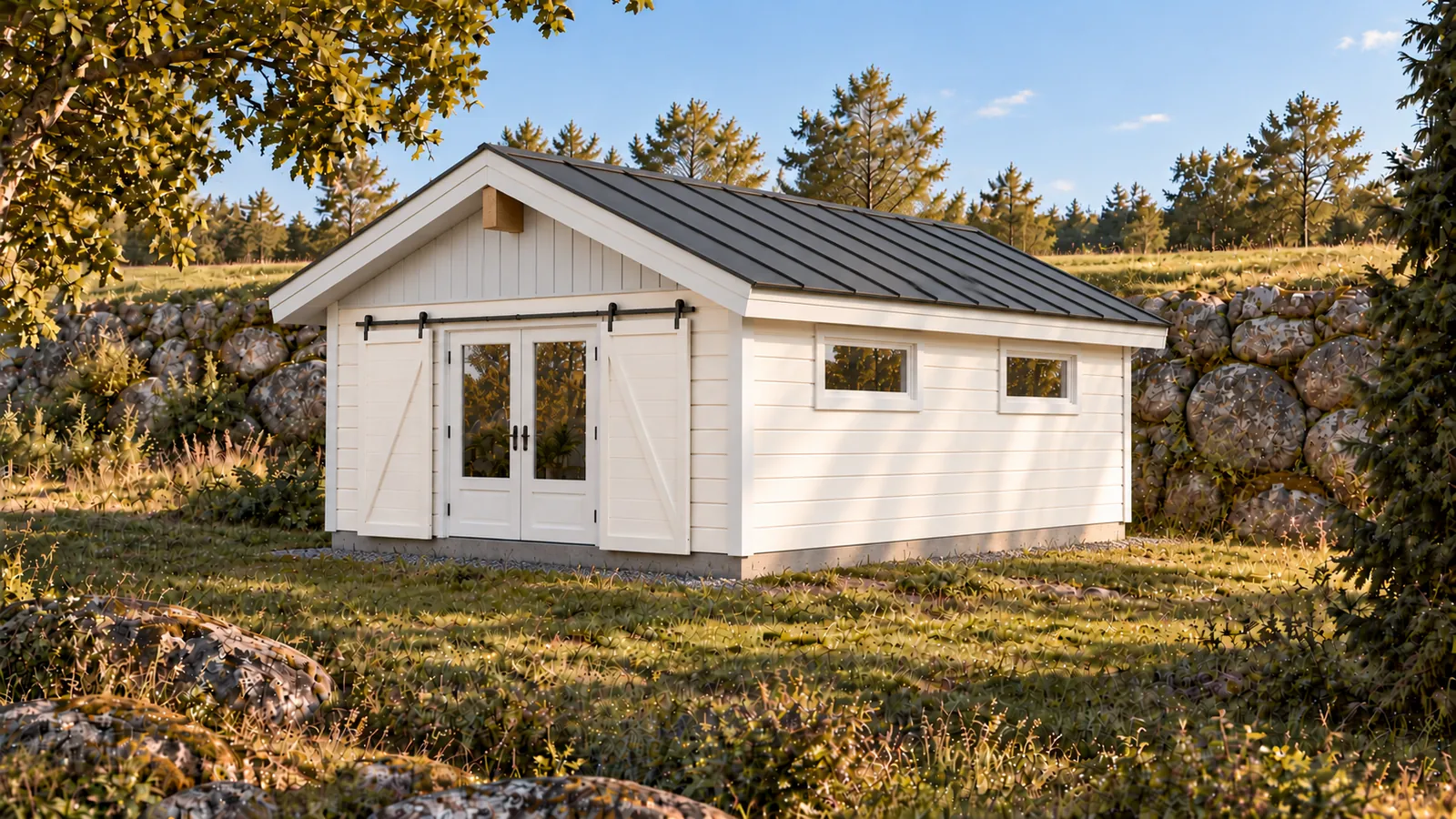
- 5 × 6 m
- Wall footprint, gable to the lake
- 22°
- Roof pitch, ridge 3595 mm above floor
- 194
- Framing members in the model
- 8
- A3 drawing sheets at 1:25
- 32 / 32
- Structural contact points checked, all passing
01 · The sketch
It started with a few lines.
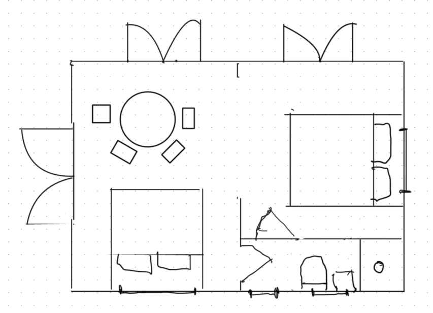
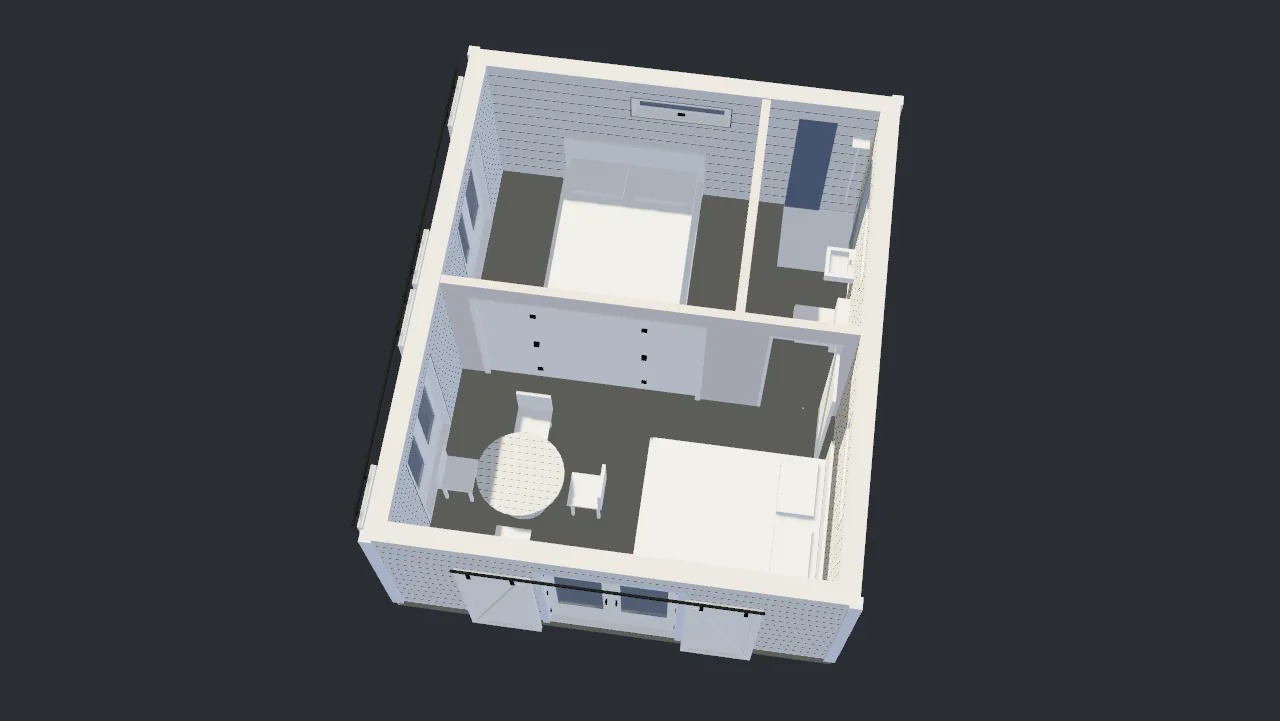
The brief was small: a 5 × 6 m guest cottage on a lakeside plot, with a rock wall behind it and the water in front. The plan arrived as a quick hand sketch. It showed two rooms, two pairs of doors to the west and one at the south gable, a round table with four chairs, two beds and a compact bathroom.
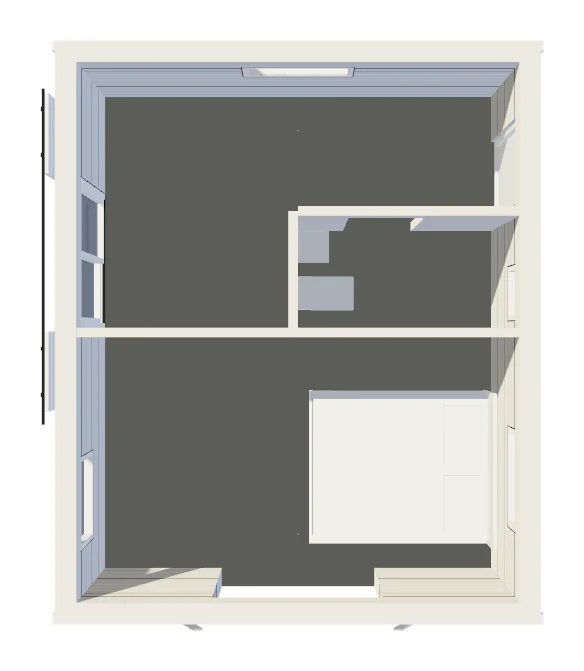
The agent read the sketch as intent and did not trace it as geometry. The furniture became conceptual space reservations, and the model marks them as grounded only in the supplied sketch. That mark stays until a real product replaces each piece.
02 · Iterating with the agent
Every revision was a conversation, and every answer was checked.
Each round started with a plain-language request. The agent changed the model, checked the result, updated the drawings and kept the previous version for comparison. The requests below are summarised from the project's revision log. Tags show which of Talos3D's strengths each step relied on.
-
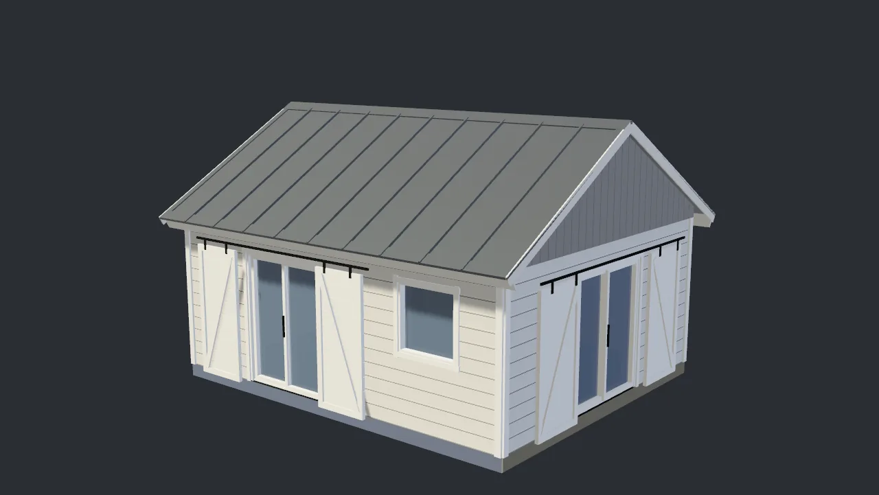
A 5 × 6 m cottage with a gable roof, patio doors to the west and south and high windows to the east.
The agent modelled the walls, roof and openings. Doors and windows are reusable designs, sized from a Swedish manufacturer's catalogue from the first pass.
Checked: first elevations and a window and door schedule.
-
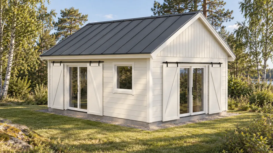
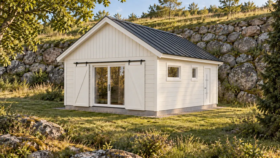
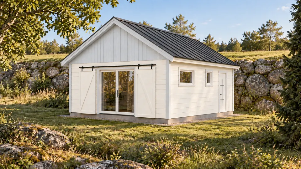
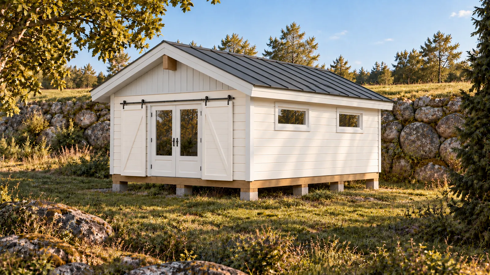
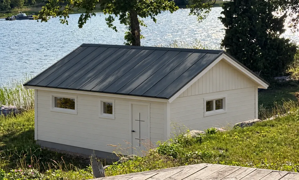
Put it on the actual plot, with the rock wall to the north and the lake to the south.
The agent turned the building, added the 2.5 m rock wall with a flat terrace above it and moved the trim and gable boarding to a pale grey.
Checked: the site illustration was regenerated from a fresh model view at each step.
-
Here is the plan I want. (the sketch above)
The agent added interior walls, the bathroom, beds, the table and chairs, plus shared designs for the patio doors and light windows. The first five-sheet drawing set followed.
Checked: saved, reopened, and confirmed every drawing still matched the model.
-
Use doors and windows we can actually order.
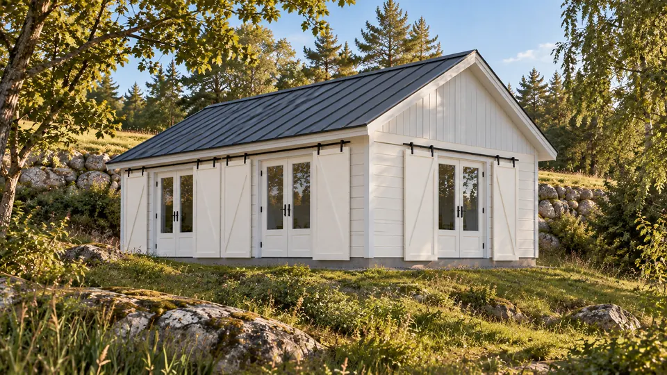
The agent matched the patio doors and high windows to catalogue sizes and derived the narrower west doors from the south door's design. It hung the west sliding shutters on one shared 5640 mm track.
Checked: the south door size accepted by the supplier's public configurator (no order placed), and shutter travel against every opening.
-
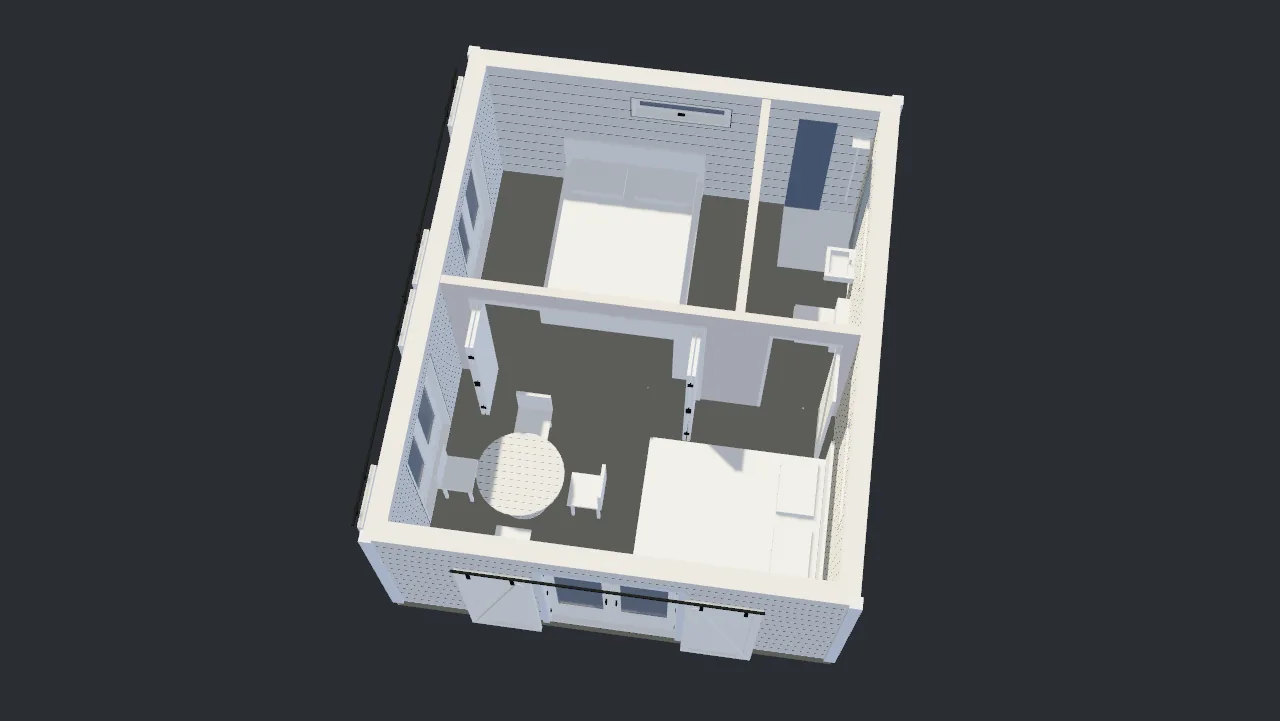
Let the two rooms open into one.
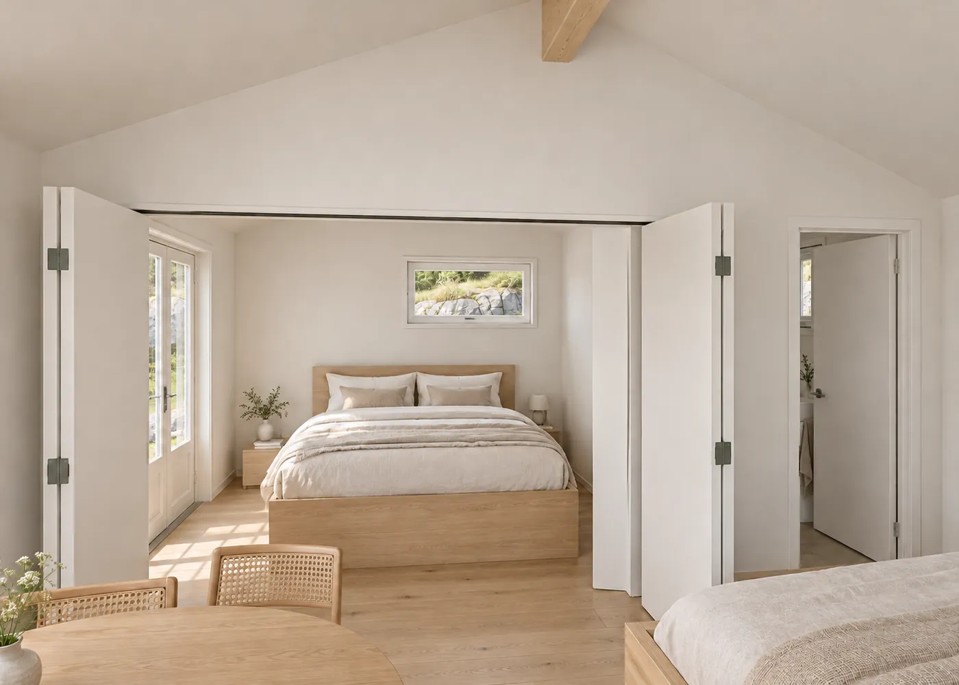
The agent replaced the divider with a four-leaf folding partition on standard hardware, giving a 2337 mm clear opening.
Checked: each folding pair swept through 361 positions from 0° to 90° against every bed, chair and fitting.
-
Fix the bathroom door swing.
The agent turned the south bathroom door to swing inward.
Checked: clearance between that door and the south bed went from 40 mm to 750 mm.
-
Lower the roof, and show me a slab versus piers.
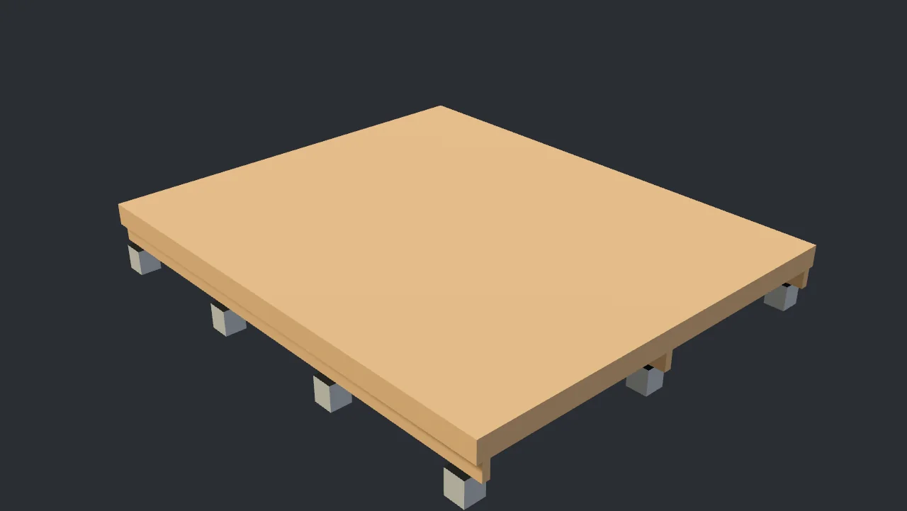
The agent cut the pitch from 30° to 22°, lowering the ridge by 442 mm. It made the three high windows copies of one 1180 × 580 design and built a pier variant with 12 piers, three bearers and a joisted floor.
Checked: the pier floor sits 577 mm above the slab floor, derived on the drawing as 300 + 220 + 220 + 23 + 14 − 200.
-
Frame it, and insulate the roof.
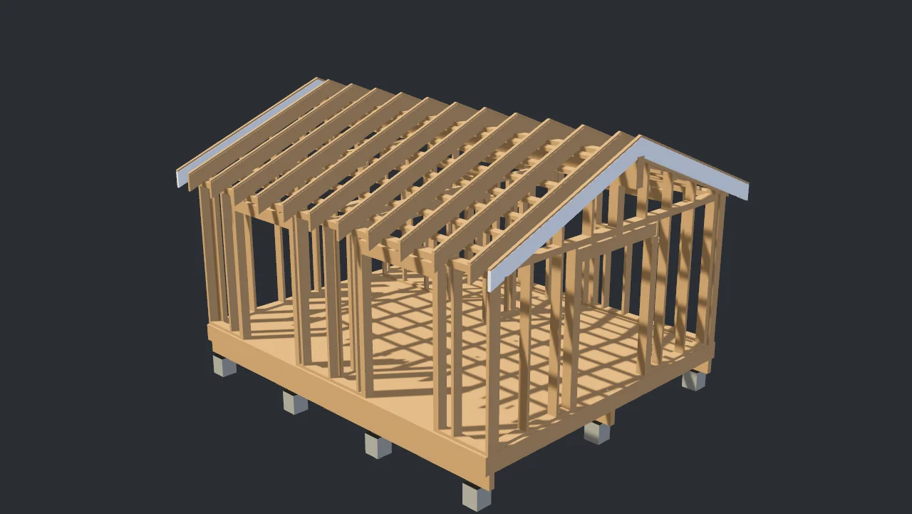
The agent added studs, plates, headers, gable framing and a glulam ridge: 194 framing members. A vaulted roof with 220 + 45 mm of insulation raised the ridge by 63 mm. Three drawing sets followed, for the slab, the piers and the structure.
Checked: all 32 points where one structural member rests on another pass, and the saved model was checked again after reopening.
-
Show me what it will feel like.
The agent made site and interior studies from fresh model exports and saved views that reveal the frame in two clicks.
Checked: model geometry unchanged, so the drawings stay valid.
03 · Massing & structure
One model, from massing to the last stud.
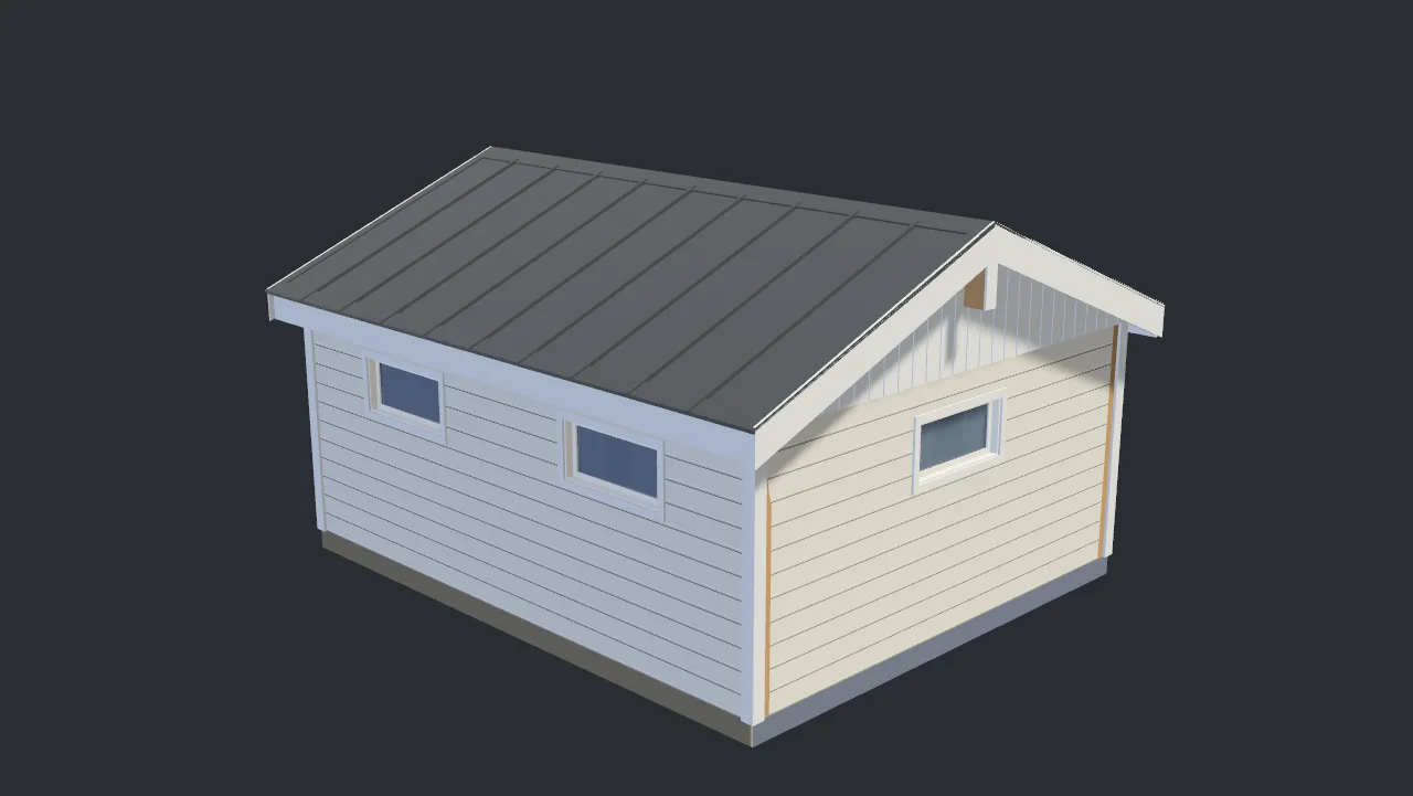
The massing and the frame are not separate files that drift apart. Walls, roof layers, openings and members live in one model, sorted into groups you can show or hide. Hide the shell to see the frame, or switch foundations to compare the slab with the piers.
- 22° roof Ridge 3595 mm above finished floor
- 2300 mm Clear height at the eaves, open to the ridge
- 220 + 45 mm Roof insulation under a glulam ridge
- Slab or 12 piers Pier floor 577 mm higher
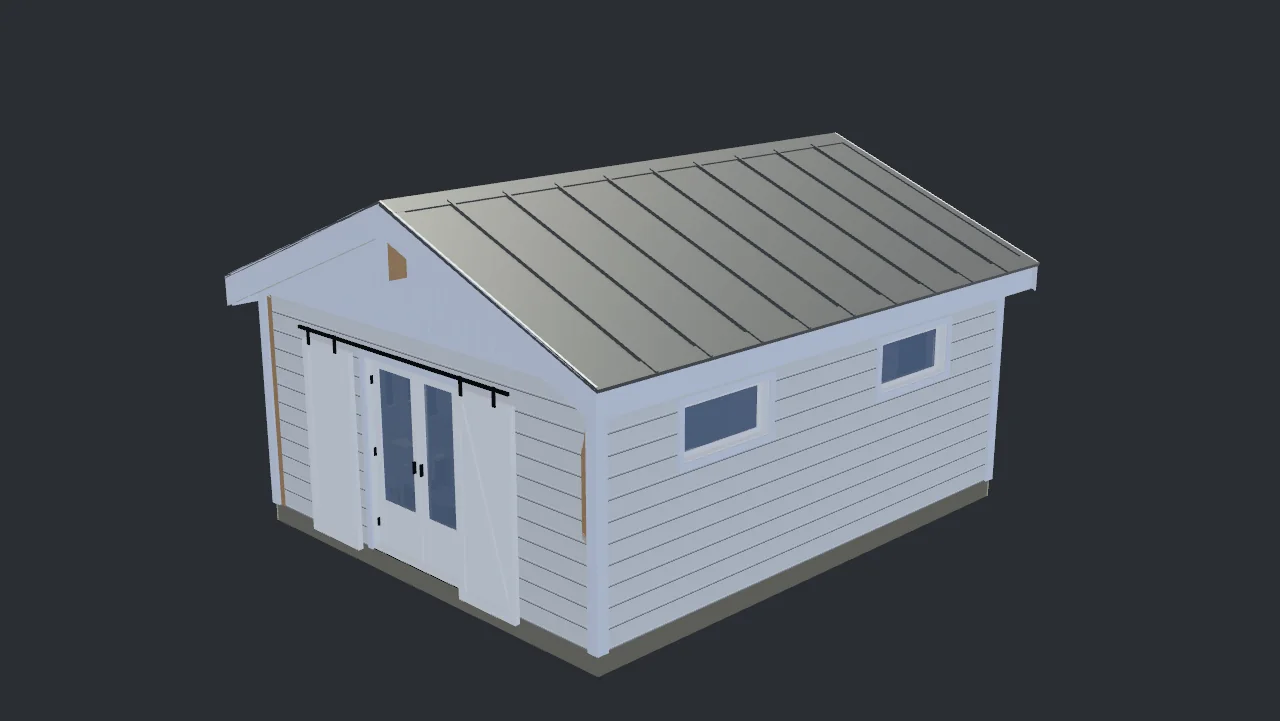
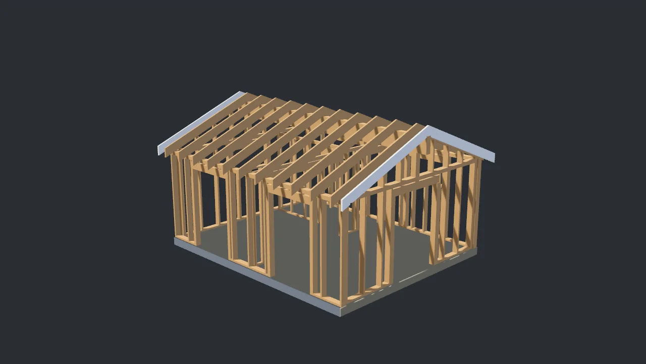
Screenshots straight from Talos3D, Revision I.
04 · Blueprints
A complete A3 drawing set, projected from the model.
Every line on these sheets is projected from the model. Opening marks, dimensions and product notes come from the same parts you see in 3D, so the drawings and the model stay in agreement. Whenever the model changed, the set was re-issued and checked page by page.
Sheets are in Swedish, at 1:25 on A3. Select one to enlarge it.
05 · On site & inside
Pictures that stay true to the model.
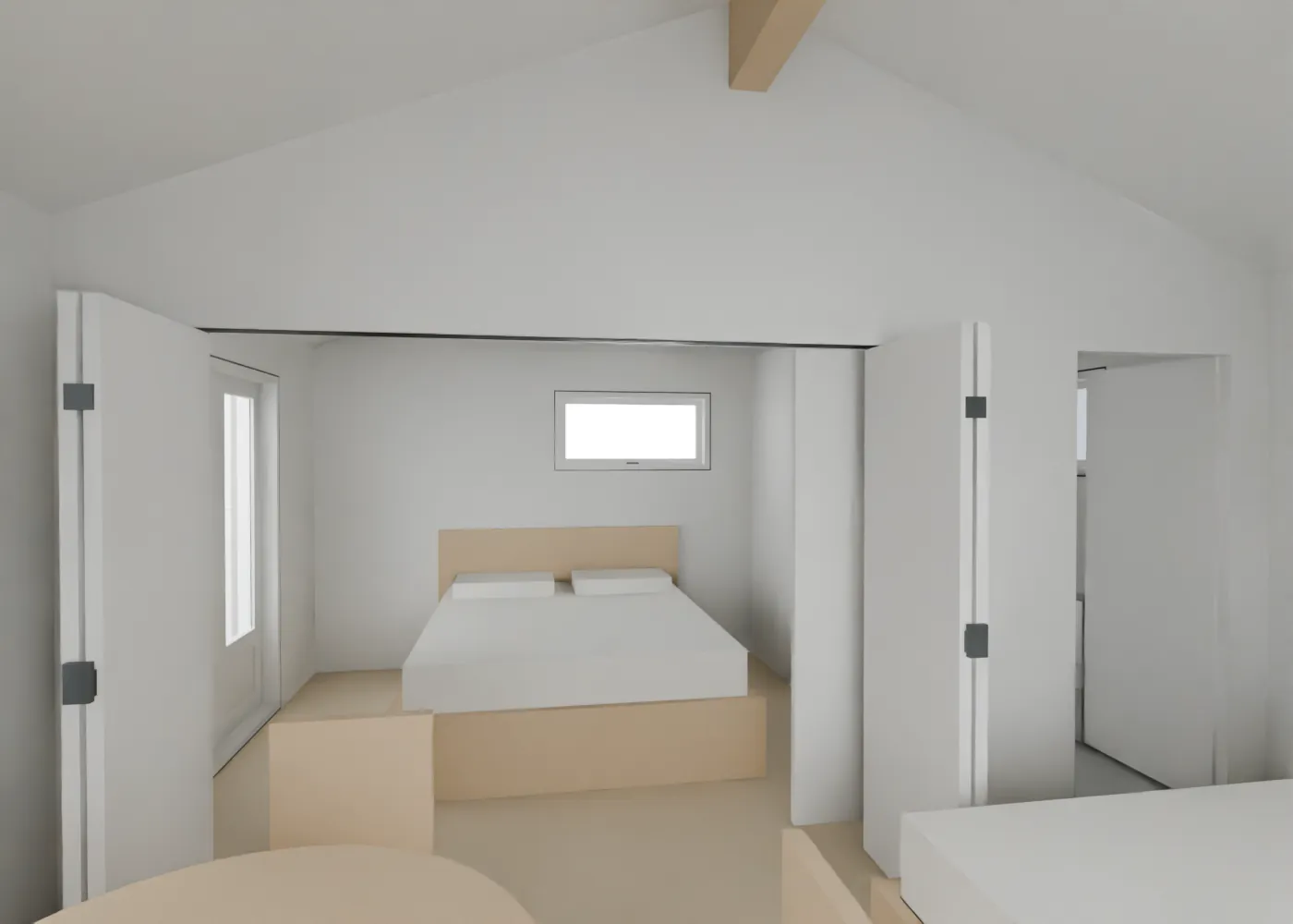
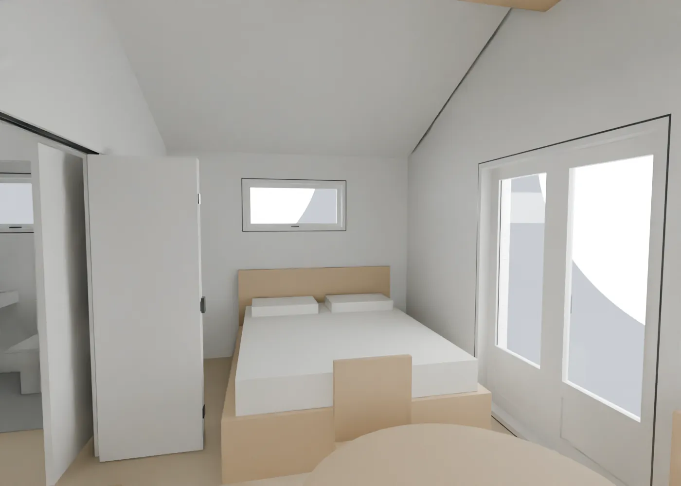
Each illustration started from a fresh model view. An image model added the lakeside setting and the materials, under instructions to keep every door, window, pitch and dimension as modelled. Switch any view to see the model capture it came from.
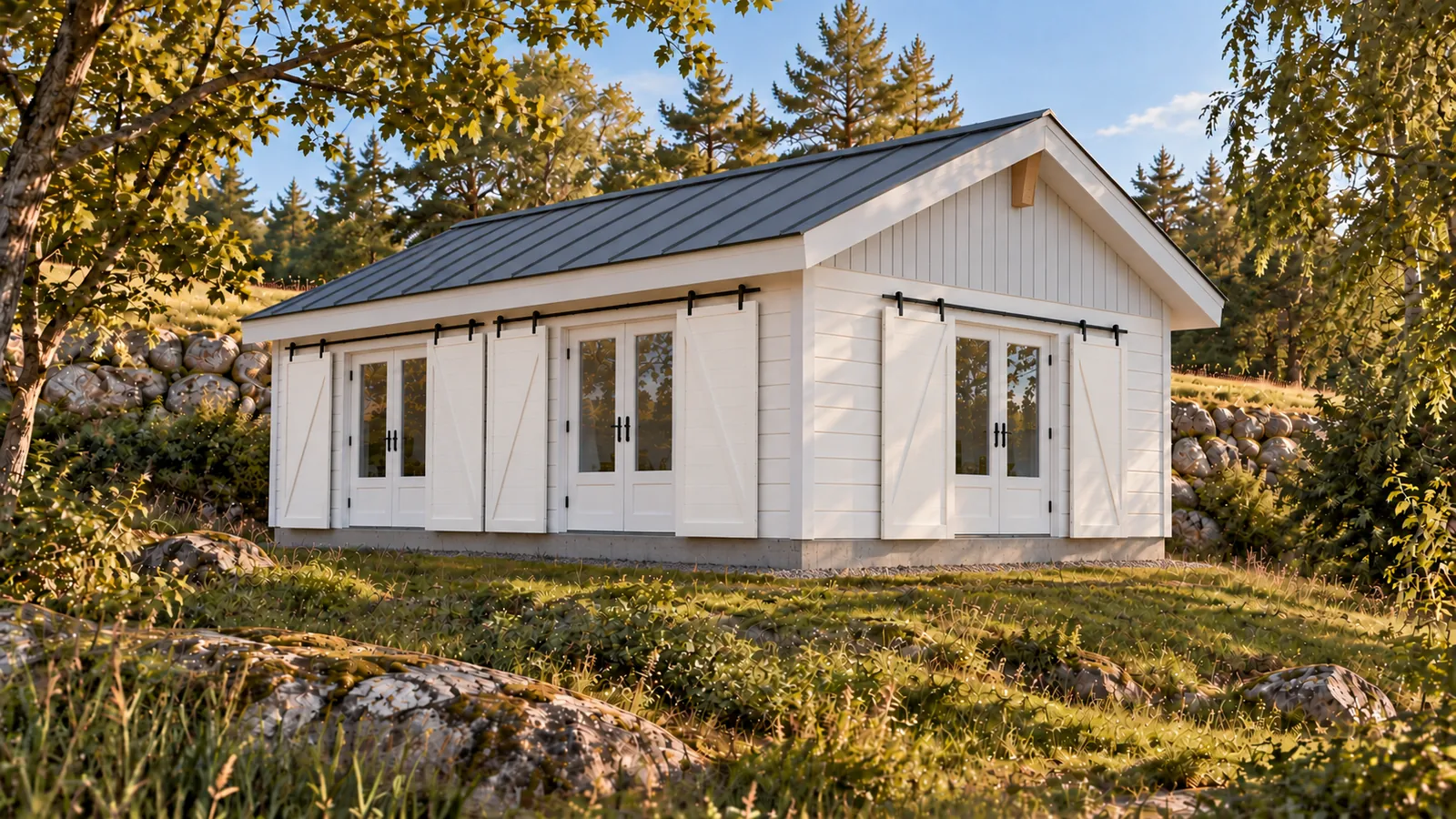
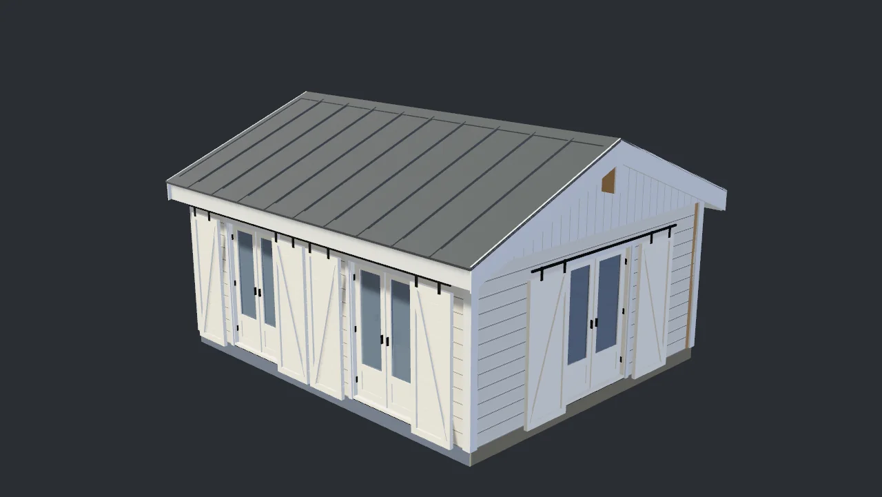
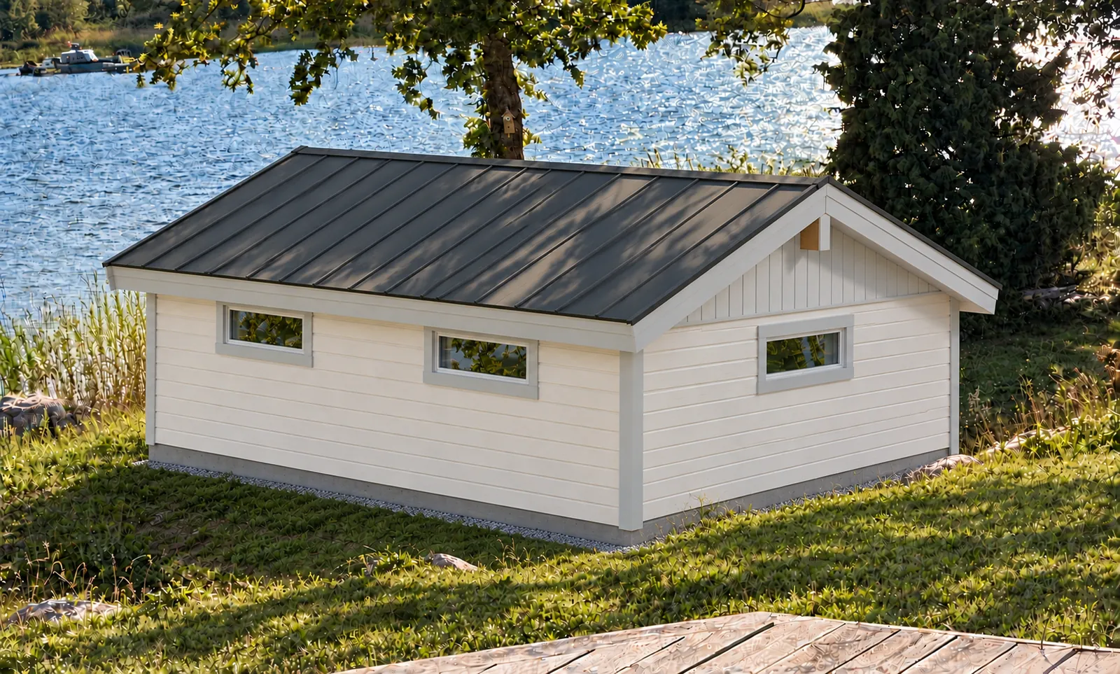
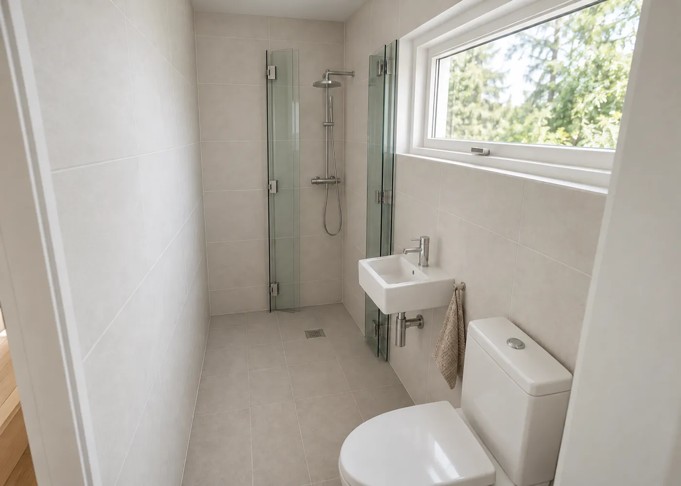
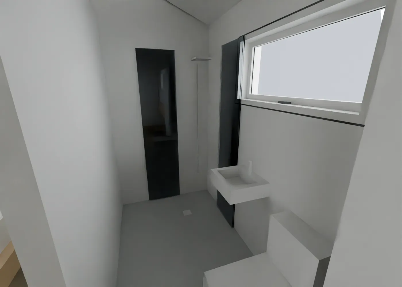
Inside the 30 m²
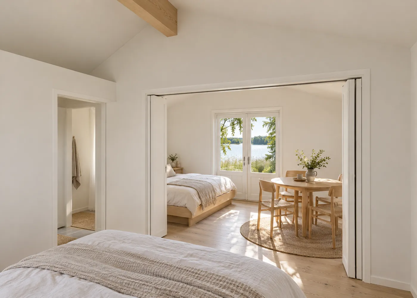
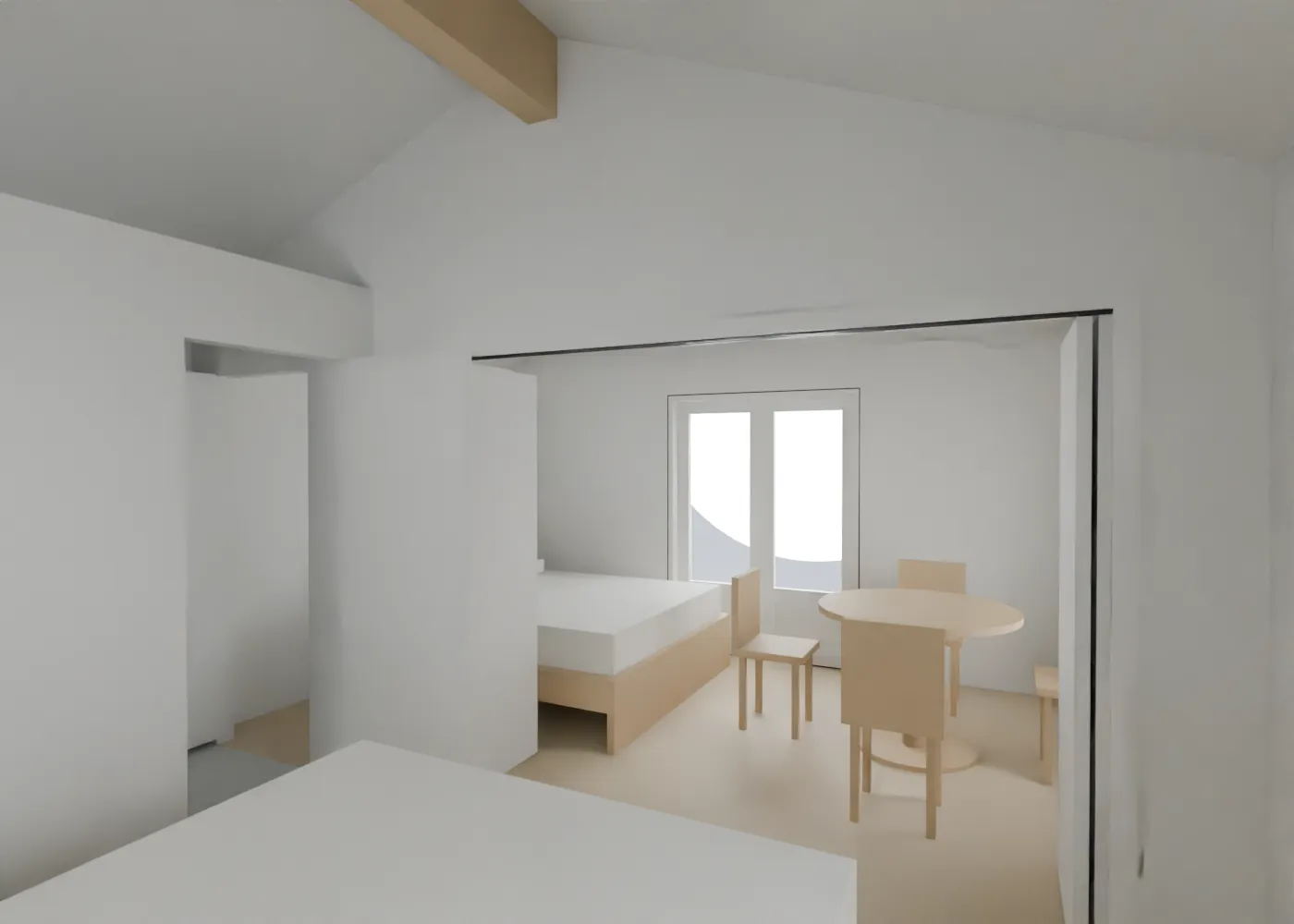
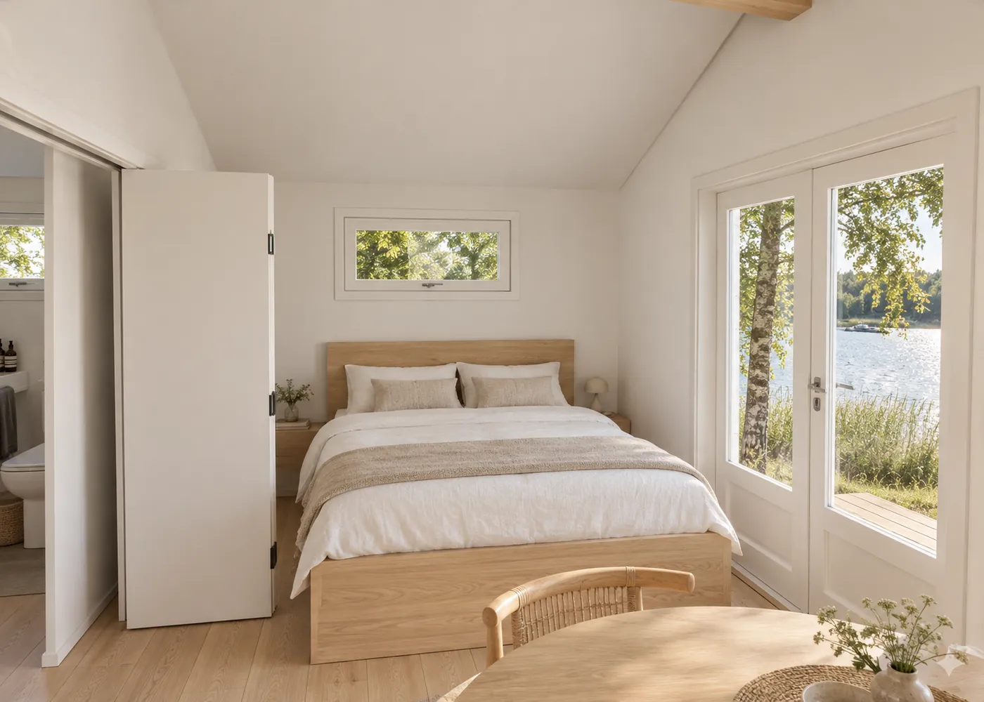
The interior studies follow the same rule. The model fixed the camera, walls, openings, vaulted ceiling and furniture positions. Image generation proposed only the finishes: warm white walls, pale oak and linen. Drag to compare.
 Model
Illustration
Model
Illustration
 Model
Illustration
Model
Illustration
 Model
Illustration
Model
Illustration
 Model
Illustration
Model
Illustration
How the picture evolved
- First massing
 On the real site
- Orientation fixed
- Grey trim
 Rev G
Rev G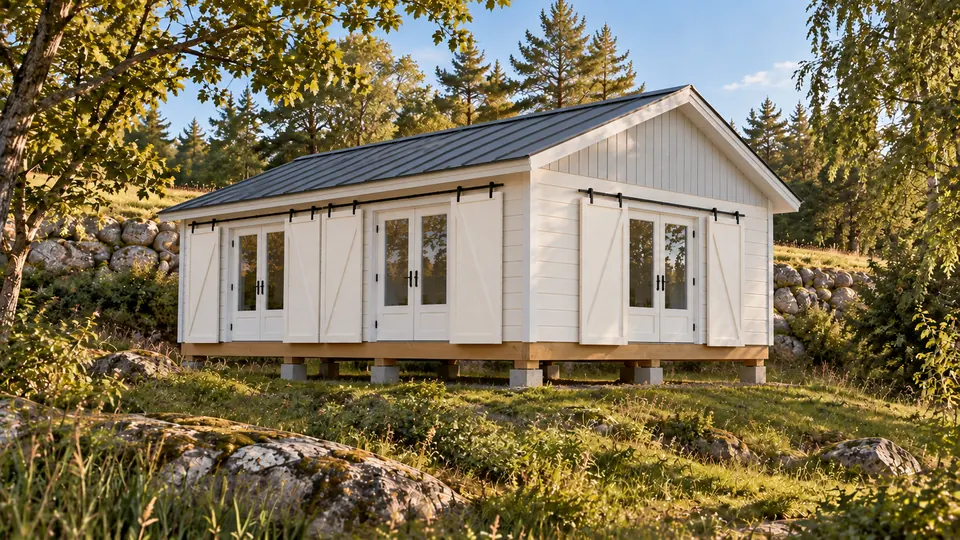 Rev H piers
- Rev I
Delivered
What two evenings of conversation produced.
One hand sketch became a complete, consistent design package. Everything below comes from the same model, so it all stays in step when anything changes.
The drawings are proposal drawings, ready for a structural engineer to take forward.
Design
- A complete 3D model: walls, roof, doors, windows, rooms and bathroom
- Doors and windows sized to real catalogue products
- A folding wall that opens two rooms into one, tested against the furniture
- Site and interior studies true to the model
Structure and drawings
- A full timber frame of 194 members, with every bearing point checked
- An insulated vaulted roof at 22°, and two foundation options
- Eight A3 sheets at 1:25: elevations, plan, roof section and framing
- A window and door schedule
Your project next
Explore your own ideas with Talos3D.
We are opening the beta to a small group of homeowners, architects and builders. Bring a sketch, a site or just an idea.